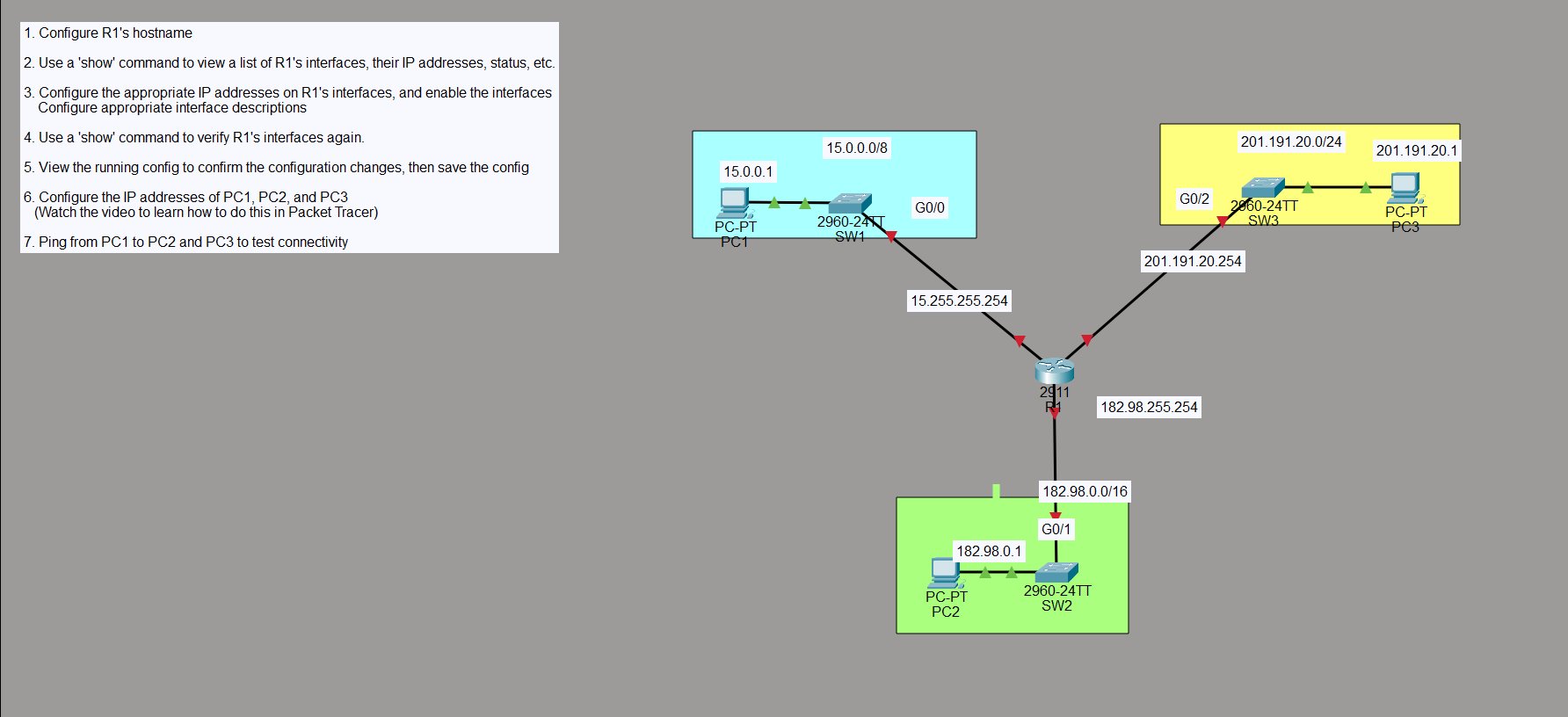
Objective
Configure a router to connect three separate subnets and verify that end devices can reach each other across them. This is the foundation of routing — a router with one interface per subnet, each interface acting as the default gateway for that subnet’s hosts.
R1’s three interfaces:
- G0/0 → 15.255.255.254/8 → SW1 → PC1 (15.0.0.1)
- G0/1 → 182.98.255.254/16 → SW2 → PC2 (182.98.0.1)
- G0/2 → 201.191.20.254/24 → SW3 → PC3 (201.191.20.1)
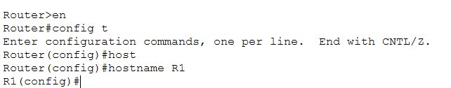
Step 1 — Set the Hostname
Router> en
Router# config t
Router(config)# hostname R1
R1(config)#
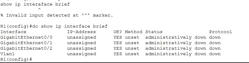
Step 2 — View Interfaces Before Configuration
Before touching anything, check the current state of R1’s interfaces:
R1(config)# do show ip interface brief
Interface         IP-Address    OK? Method  Status                Protocol
GigabitEthernet0/0  unassigned  YES unset   administratively down down
GigabitEthernet0/1  unassigned  YES unset   administratively down down
GigabitEthernet0/2  unassigned  YES unset   administratively down down
Vlan1               unassigned  YES unset   administratively down down
All three interfaces are unassigned and administratively down — Cisco routers ship with interfaces shut down by default. Nothing will pass traffic until they’re explicitly enabled.
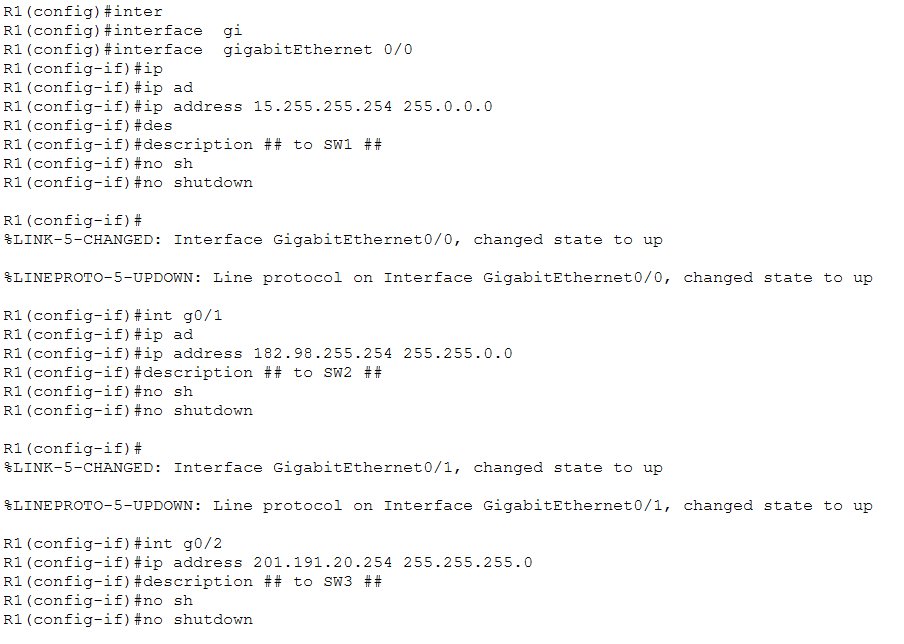
Step 3 — Configure IP Addresses and Enable Interfaces
Configure each interface with its IP address, a description, and bring it up with no shutdown:
R1(config)# interface gigabitEthernet 0/0
R1(config-if)# ip address 15.255.255.254 255.0.0.0
R1(config-if)# description ## to SW1 ##
R1(config-if)# no shutdown

%LINK-5-CHANGED: Interface GigabitEthernet0/0, changed state to up
%LINEPROTO-5-UPDOWN: Line protocol on Interface GigabitEthernet0/0, changed state to up

R1(config-if)# int g0/1
R1(config-if)# ip address 182.98.255.254 255.255.0.0
R1(config-if)# description ## to SW2 ##
R1(config-if)# no shutdown

%LINK-5-CHANGED: Interface GigabitEthernet0/1, changed state to up
%LINEPROTO-5-UPDOWN: Line protocol on Interface GigabitEthernet0/1, changed state to up

R1(config-if)# int g0/2
R1(config-if)# ip address 201.191.20.254 255.255.255.0
R1(config-if)# description ## to SW3 ##
R1(config-if)# no shutdown
The %LINK-5-CHANGED and %LINEPROTO-5-UPDOWN messages confirm each interface comes up as soon as no shutdown is entered. Descriptions are optional but good practice — they make the config readable at a glance.
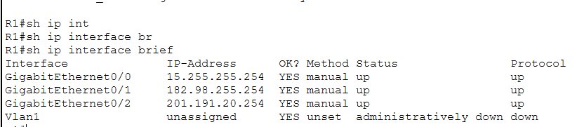
Step 4 — Verify Interfaces After Configuration
R1# sh ip interface brief
Interface         IP-Address       OK? Method  Status    Protocol
GigabitEthernet0/0  15.255.255.254 YES manual  up        up
GigabitEthernet0/1  182.98.255.254  YES manual  up        up
GigabitEthernet0/2  201.191.20.254  YES manual  up        up
Vlan1               unassigned      YES unset   admin down down
All three interfaces are now up/up with their assigned IPs. The Method column shows manual — meaning the addresses were configured by hand, not via DHCP.
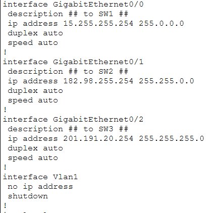
Step 5 — View Running Config and Save
show run confirms the interface configuration looks correct:
interface GigabitEthernet0/0
 description ## to SW1 ##
 ip address 15.255.255.254 255.0.0.0
 duplex auto
 speed auto
!
interface GigabitEthernet0/1
 description ## to SW2 ##
 ip address 182.98.255.254 255.255.0.0
 duplex auto
 speed auto
!
interface GigabitEthernet0/2
 description ## to SW3 ##
 ip address 201.191.20.254 255.255.255.0
 duplex auto
 speed auto
Then save:
R1# write
Building configuration...
[OK]
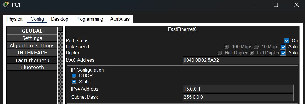
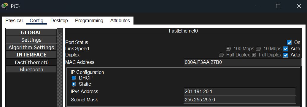
Step 6 — Configure PC IP Addresses
Each PC needs a static IP in its subnet. Done through the Config → FastEthernet0 tab in Packet Tracer:
PC1 — IP: 15.0.0.1 / Mask: 255.0.0.0 / Gateway: 15.255.255.254
PC2 — IP: 182.98.0.1 / Mask: 255.255.0.0 / Gateway: 182.98.255.254

PC3 — IP: 201.191.20.1 / Mask: 255.255.255.0 / Gateway: 201.191.20.254
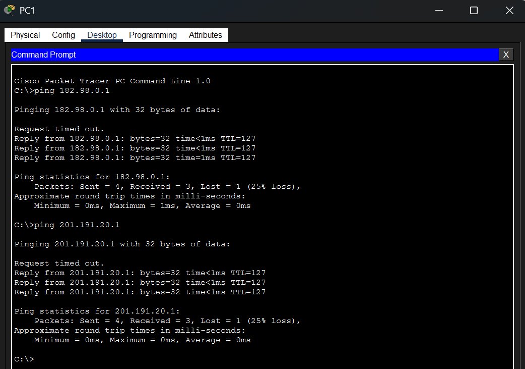
Step 7 — Test Connectivity
From PC1, ping PC2 and PC3 to confirm routing is working across all three subnets:
C:\>ping 182.98.0.1

Request timed out.
Reply from 182.98.0.1: bytes=32 time<1ms TTL=127
Reply from 182.98.0.1: bytes=32 time<1ms TTL=127
Reply from 182.98.0.1: bytes=32 time=1ms TTL=127

C:\>ping 201.191.20.1

Request timed out.
Reply from 201.191.20.1: bytes=32 time<1ms TTL=127
Reply from 201.191.20.1: bytes=32 time<1ms TTL=127
Reply from 201.191.20.1: bytes=32 time<1ms TTL=127
Both pings succeed. The first packet times out on each — that’s ARP resolving the MAC address before the ICMP echo can be sent, which is normal. TTL=127 confirms the traffic is passing through one router hop (started at 128, decremented by 1).
Key Takeaways
- Router interfaces are shut down by default — always need
no shutdownto bring them up - Each interface is its own subnet — the router connects them and forwards traffic between them
show ip interface briefis the go-to command for a quick status check on all interfaces at once- Descriptions on interfaces (
description ## to SW1 ##) are optional but make configs much easier to read and troubleshoot - The first ping often times out — ARP has to resolve the destination MAC before ICMP can flow, which takes one packet’s worth of time
- TTL=127 on the replies tells you the traffic crossed exactly one router (128 default TTL - 1 hop = 127)