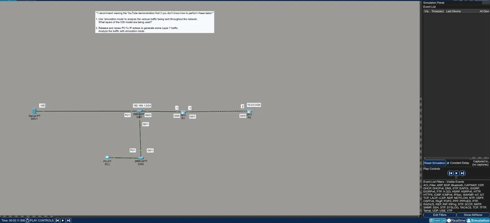
Objective
Use Packet Tracer’s simulation mode to observe the various protocols running on a small network and identify which OSI layers are involved. Then generate Layer 7 traffic by releasing and renewing PC1’s IP address via DHCP and inspect the resulting packets.
The topology is a simple two-router network: SRV1 → SW1 → R1 — R2 → SW2 → PC1, with subnet 192.168.1.0/24 on the left and 10.0.0.0/24 on the right.
Part 1 — Observing Background Traffic
With simulation mode running and no manual traffic generated, the event list starts filling up on its own. Two protocols appear immediately:
STP (Spanning Tree Protocol)
- Running on SW1 and SW2
- Operates at Layer 2 — the switches process it at the data link layer only. Layers 3 and above are blank in the OSI model panel, which makes sense: STP has no IP header, no transport layer, nothing above Layer 2.
OSPF (Open Shortest Path First)
- Generated by R1 — OSPF Hello packets being multicast out GigabitEthernet0/0
- Operates at Layers 1, 2, and 3 — routers process up through the network layer
- The PDU details confirm: Layer 2 shows the Ethernet II header with the OSPF multicast MAC (
0100.5E00.0005), Layer 3 shows the IP packet, Layer 1 shows the physical port
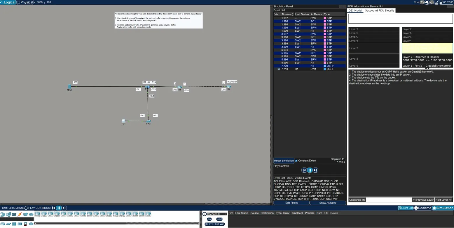
The key observation here: layer processing stops at the layer relevant to the device. Switches only process up to Layer 2. Routers process up to Layer 3. Neither STP nor OSPF reaches Layer 7 in this topology — they’re infrastructure protocols, not application traffic.
Part 2 — Generating Layer 7 Traffic with DHCP
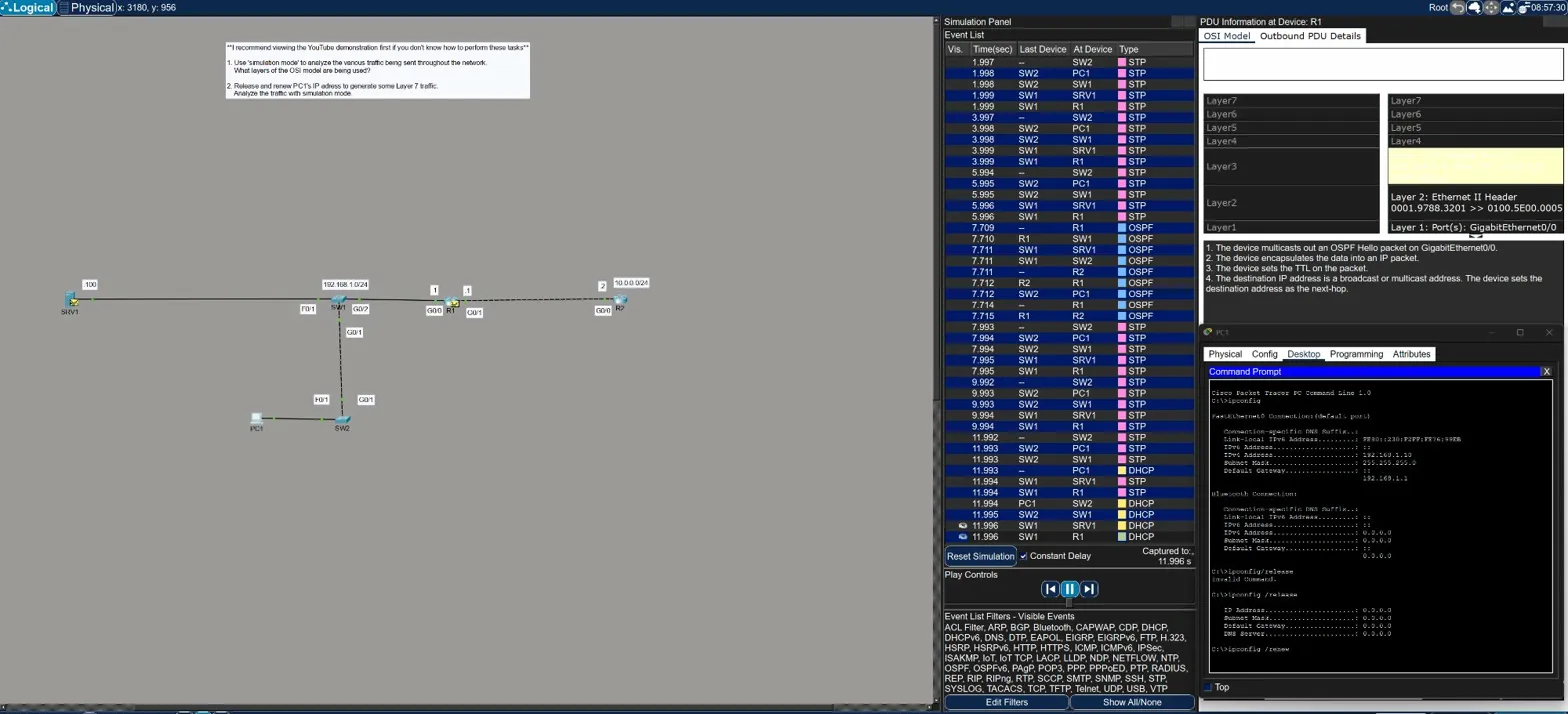
To see all seven layers in action, the lab asks you to release and renew PC1’s IP address from the command prompt. This forces a DHCP exchange, which is an application-layer protocol.
From PC1’s command prompt:
ipconfig /release
ipconfig /renew
After releasing, PC1’s IP drops to 0.0.0.0 — it has no address. The renew triggers a full DHCP handshake, and the simulation panel fills up with DHCP events.
Clicking into the DHCP packet at R1 shows the full OSI stack populated:
| Layer | Details |
|---|---|
| Layer 7 | DHCP — Server 0.0.0.0, Client 0.0.0.0 (DISCOVER packet) |
| Layer 4 | UDP — Src Port 68, Dst Port 67 |
| Layer 3 | IP — Src 192.168.1.10, Dst 255.255.255.255 |
| Layer 2 | Ethernet II — 0030.F276.99EB >> FFFF.FFFF.FFFF (broadcast) |
| Layer 1 | GigabitEthernet0/0 receives the frame |
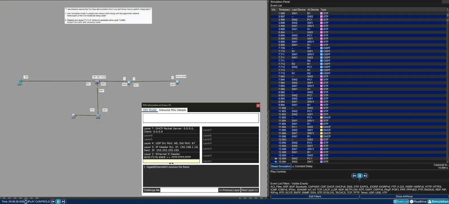
This is the first time in the labs where all seven layers light up. The broadcast destination at Layer 2 (FFFF.FFFF.FFFF) and Layer 3 (255.255.255.255) makes sense — PC1 doesn’t know the DHCP server’s address yet, so it broadcasts to find one.
Key Takeaways
- Simulation mode lets you step through traffic event by event and inspect each PDU layer by layer — it’s the best tool in Packet Tracer for understanding what’s actually happening on the wire
- Layer processing reflects device type — switches stop at Layer 2, routers stop at Layer 3, end devices go all the way to Layer 7
- STP is Layer 2 only — no IP header, no transport, just Ethernet frames between switches
- OSPF uses Layers 1–3 — it’s a routing protocol, so it needs Layer 3, but there’s no Layer 4 (it runs directly over IP, not TCP or UDP)
- DHCP uses all layers — as an application protocol it touches everything from the physical port up through Layer 7
ipconfig /releaseandipconfig /reneware useful tools for forcing DHCP traffic on demand — handy for both labs and real troubleshooting