Objective
Understand how switches build and use MAC address tables. The lab starts with both switches having completely empty MAC address tables and all PCs having empty ARP tables — a clean slate. The goal is to observe what happens when traffic flows, how switches learn which MAC address lives on which port, and how to read and clear the MAC address table.
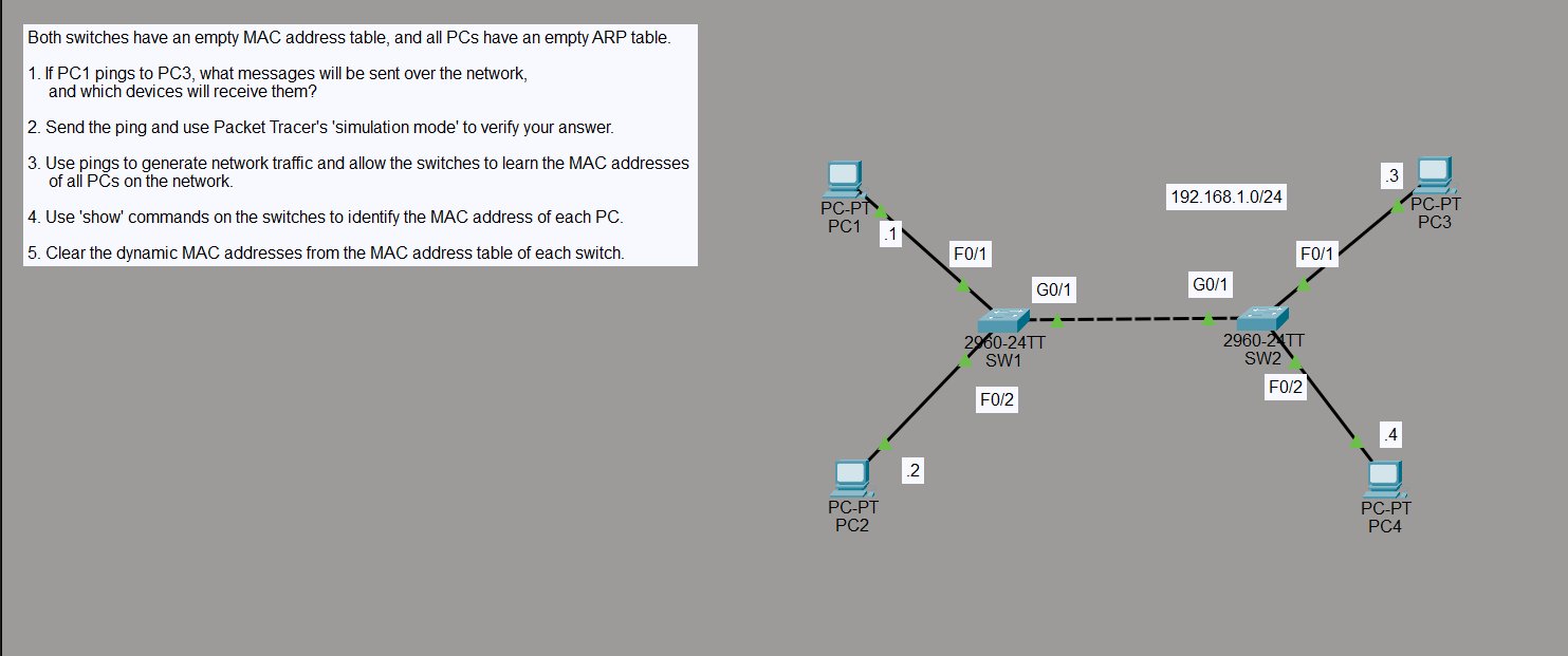
The topology is a single subnet (192.168.1.0/24) split across two 2960 switches:
- SW1 — PC1 (.1) on Fa0/1, PC2 (.2) on Fa0/2, uplink to SW2 on G0/1
- SW2 — PC3 (.3) on Fa0/1, PC4 (.4) on Fa0/2, uplink to SW1 on G0/1
Step 1 — Predict the Traffic Before Sending
Before sending anything, the question is: if PC1 pings PC3, what messages will be sent and which devices will receive them?
With empty MAC and ARP tables, PC1 doesn’t know PC3’s MAC address. It has to find it first. So the sequence is:
- ARP broadcast — PC1 sends an ARP request to
FFFF.FFFF.FFFFasking “who has 192.168.1.3?” Since it’s a broadcast, SW1 floods it out every port including the G0/1 uplink to SW2, which floods it to PC3 and PC4. - ARP reply — PC3 responds directly to PC1’s MAC with its own MAC address. Now PC1 knows where to send the ping.
- ICMP echo — PC1 sends the ping to PC3. Switches forward it based on the MAC addresses they’ve now learned.
Every device on the network receives the initial ARP broadcast — PC2 and PC4 included, even though they’re not part of the conversation.
Step 2 — Send the Ping and Verify in Simulation Mode
With simulation mode running, PC1 pings PC3:
C:\>ping 192.168.1.3
The event list tells the whole story — ARP traffic floods out first, hitting every device on both switches, then ICMP takes over once the MAC addresses are resolved.
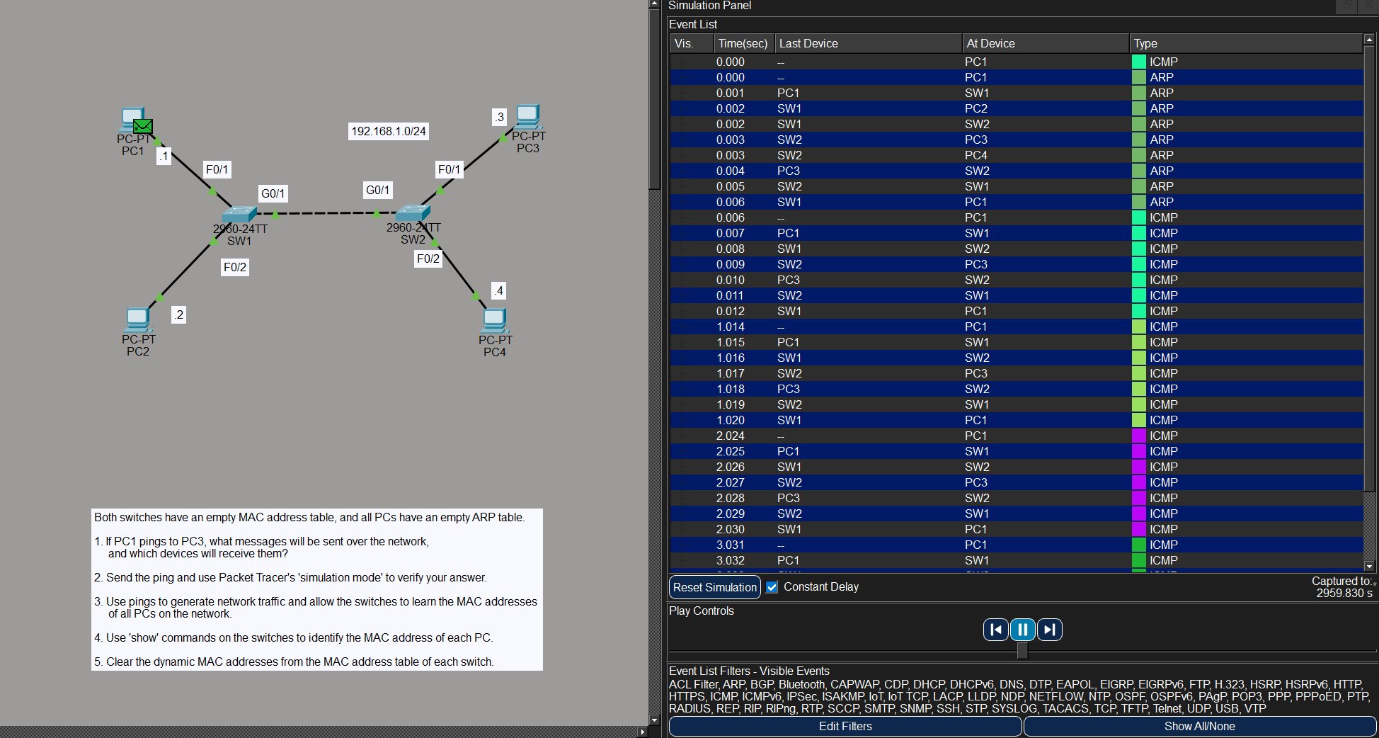
The prediction was correct. ARP goes everywhere, ICMP goes point to point.
Step 3 — Generate Traffic to Populate the MAC Tables
To get all four PCs into both switches’ MAC address tables, ping across the network from multiple PCs. PC1 pings PC3, PC2 pings PC4 — after that both switches have seen traffic from all four devices and can populate their tables.
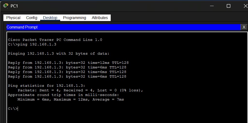
PC1 → PC3:
C:\>ping 192.168.1.3

Reply from 192.168.1.3: bytes=32 time=12ms TTL=128
Reply from 192.168.1.3: bytes=32 time=6ms TTL=128
Reply from 192.168.1.3: bytes=32 time=6ms TTL=128
Reply from 192.168.1.3: bytes=32 time=6ms TTL=128
PC2 → PC4:
C:\>ping 192.168.1.4

Reply from 192.168.1.4: bytes=32 time=12ms TTL=128
Reply from 192.168.1.4: bytes=32 time=6ms TTL=128
Reply from 192.168.1.4: bytes=32 time=6ms TTL=128
Reply from 192.168.1.4: bytes=32 time=6ms TTL=128
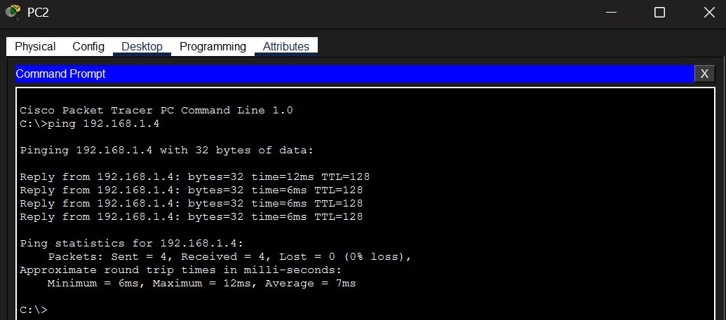
All pings succeed with 0% loss.
Step 4 — Read the MAC Address Tables
After the pings, check what each switch has learned:
SW1:
SW1# show mac address-table

          Mac Address Table
-------------------------------------------

Vlan    Mac Address       Type        Ports
----    -----------       --------    -----
   1    0001.647b.3119    DYNAMIC     Gig0/1
   1    0004.9a6e.d870    DYNAMIC     Gig0/1
   1    0060.5c56.14d3    DYNAMIC     Fa0/2
   1    00d0.d3ad.9cab    DYNAMIC     Fa0/1
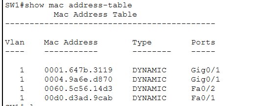
SW1 knows PC1 and PC2 directly on Fa0/1 and Fa0/2. PC3 and PC4 were learned through the G0/1 uplink — SW1 doesn’t know which port they’re actually on behind SW2, just that they’re reachable via G0/1.
SW2:
SW2# show mac add

          Mac Address Table
-------------------------------------------

Vlan    Mac Address       Type        Ports
----    -----------       --------    -----
   1    0001.647b.3119    DYNAMIC     Fa0/2
   1    0004.9a6e.d870    DYNAMIC     Fa0/1
   1    0060.5c56.14d3    DYNAMIC     Gig0/1
   1    00d0.d3ad.9cab    DYNAMIC     Gig0/1
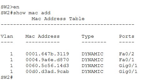
The mirror of SW1 — SW2 knows PC3 and PC4 directly, and sees PC1 and PC2 through its G0/1 uplink back to SW1. All four MACs are present on both switches.
Step 5 — Clear the MAC Address Table
To reset the dynamic entries:
SW2# clear mac address-table dynamic
SW2# show mac add

          Mac Address Table
-------------------------------------------

Vlan    Mac Address       Type        Ports
----    -----------       --------    -----

SW2#
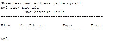
The table is empty. If traffic flows again the switch will relearn everything from scratch — the whole dynamic learning process starts over.
Key Takeaways
- Switches learn MAC addresses dynamically by examining the source MAC of incoming frames — they never need to be configured manually for this
- With an empty ARP table, a ping always triggers an ARP broadcast first — the sender has to resolve the destination MAC before it can send anything
- ARP broadcasts are flooded to every port on every switch in the same subnet — all devices receive them, not just the target
- The MAC address table maps MAC addresses to switch ports — entries learned via an uplink just point to that uplink, not the actual end device port
show mac address-table(or the shorthandshow mac add) shows all learned entries with their VLAN, type, and portclear mac address-table dynamicwipes all dynamic entries — static entries (configured manually) would survive