The Lab
This is the first lab from Jeremy’s IT Lab CCNA course. The goal is to get familiar with Cisco Packet Tracer by building a network diagram from scratch — placing devices, connecting them, and understanding the basic topology of a multi-branch enterprise network.
Starting Point
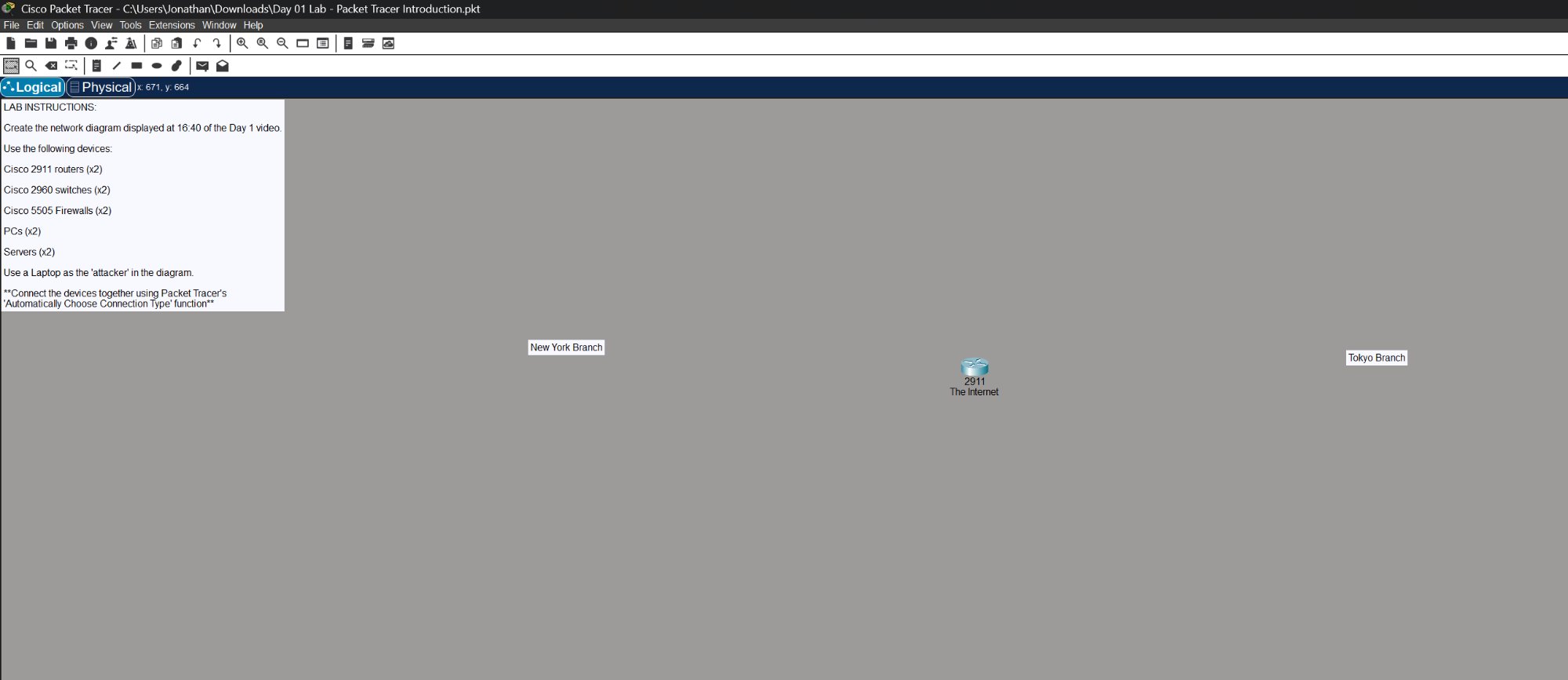
The lab starts with just a blank canvas, the instructions on the left, and a router labeled “The Internet” in the middle with two branch labels.
Lab Instructions
Build a network connecting a New York Branch and a Tokyo Branch through the internet using:
- Cisco 2911 routers (x2) — one for each branch
- Cisco 2960 switches (x2) — one for each branch LAN
- Cisco 5505 firewalls (x2) — one protecting each branch
- PCs (x2) — end devices on the New York side
- Servers (x2) — end devices on the Tokyo side
- Laptop — acting as the “attacker” connected to the internet
All devices connected using Packet Tracer’s “Automatically Choose Connection Type” function.
Completed Topology
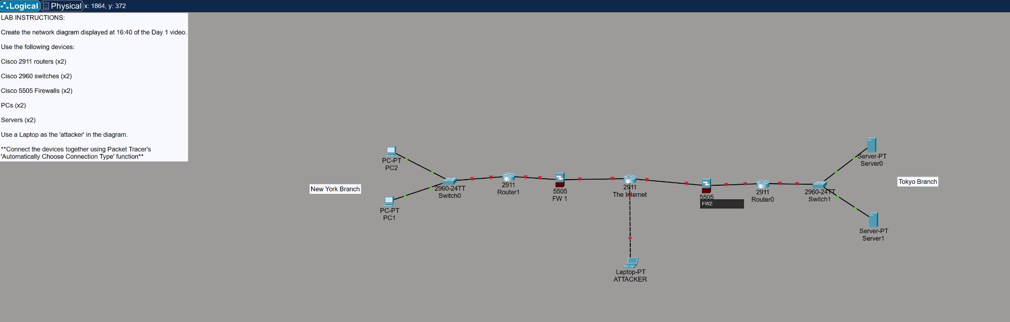
The completed network shows both branches fully connected through the central internet router:
- New York Branch — Two PCs connected to a 2960 switch, through a 2911 router, protected by a 5505 firewall before hitting the internet
- Tokyo Branch — Two servers connected to a 2960 switch, through a 2911 router, protected by a 5505 firewall before hitting the internet
- Attacker laptop — Connected directly to the internet router, simulating an external threat
What I Learned
- How to navigate Cisco Packet Tracer — device placement, cabling, and the logical vs physical view
- The basic structure of an enterprise network: end devices → switch → router → firewall → WAN
- Why firewalls sit between the internal network and the internet — they inspect and filter traffic before it reaches the router
- The difference between device types (routers, switches, firewalls) and their roles in the network
- This is day 1 of working through the full CCNA curriculum — more labs to come as I progress through the course